FAQs
The team at Keyfix have created technical guidance to answer your most frequently asked questions. Find all the answers you’ll need below.
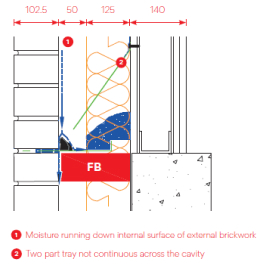
What is the function of a Cavity Tray?
A Cavity Tray is required over all bridges or penetrations of the cavity within an external wall.
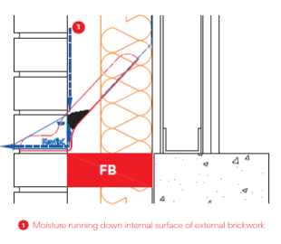
Its primary function is to capture moisture running down the internal surface of the external skin of masonry, and moisture dripping off wall ties within the nominal 50mm 'clear cavity'.
Once captured, this moisture must be restricted from travelling horizontally along the length of the tray and instead must be expelled out of the cavity via weep vents placed at specified centres.
It is therefore essential that the Cavity Tray is continuous across the 'clear cavity' to ensure that all moisture captured is directed outwards and not obstructed by mortar droppings, creating a route inwards which could in turn saturate insulation etc.
Furthermore, it is important to ensure the horizontal section of a Cavity Tray is continuous and does not have any perforations which could redirect the captured moisture inwards. It is also essential that a tray has no perforations in order to prevent rising damp.
Key:
1. Moisture running down internal surface of external skin
2. Two part tray not continuous across the cavity
Can one Non-combustible Cavity Tray be installed over several items within the cavity?
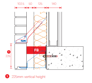
It is acceptable to protect more than one element i.e. fire barrier & masonry support, with a single Non-combustible Cavity Tray, provided the lowest item requiring protection is located within a maximum vertical height of 225mm from the Cavity Tray.
A NCCT should be installed as close as possible to the item it is protecting.
The logic behind this dimension is driven by brickwork bonds. If a soldier course was to be built over the item to be protected, the closest measurement the NCCT can be installed is 225mm.
Details which are outside of the above should be given additional consideration in relation to the area of masonry above, in order to assess exposure to moisture volumes and mortar droppings etc.
Key:
1. 225mm vertical height
Does a Cavity Tray need to be fixed to, or supported by the internal skin?
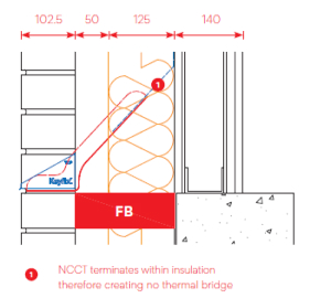
All major Warranty Providers agree that where a Cavity Tray is rigid enough to be self-supporting across the clear cavity, it does not need to be fixed to the internal skin for support. This may differ in areas of very high exposure to wind driven rain such as the Scottish Highlands etc. The Keyfix NCCT system with its integral Stop Ends preformed on each tray, is rigid enough to be self-supporting and therefore does not need to be fixed to, or supported by the internal skin.
This in turn eliminates issues such as Thermal Bridging and Differential Movement which have been identified by Warranty Providers as an area of concern for metal cavity tray systems which are fixed to the internal skin. Cavity Tray systems which do not require support from the internal skin are known to be substantially easier and less expensive to install, whilst reducing interferences as a result of deviations in cavity width due to construction tolerances.
Key:
1. NCCT terminates within insulation therefore creating no thermal bridge
Is a Non-combustible Cavity Tray required between two skins of masonry just above ground level?
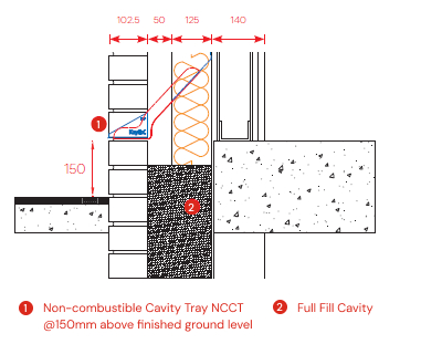
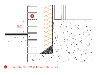
Cavity Trays when built between two skins of masonry are exempt from the updated Document B, however some design teams and clients will insist on NCCT's throughout the building to provide continuity of detailing. External walls built with two skins of masonry which have adequate provision for cavity drainage and mortar droppings may not be required (in discussion with Project Design Team / Client and Warranty Provider etc) to use a NCCT and instead install a horizontal Non Combustible Damp Proof Course (NCDPC) above finished ground level as shown.
Key:
1. Non-combustible Cavity Tray NCCT @150mm above finished ground level (FGL)
2. Full Fill Cavity
3. Horizontal NCDPC @ 150mm above FGL
Key:
1. Non-combustible Cavity Tray NCCT @150mm above finished ground level (FGL)
2. Full Fill Cavity
3. Horizontal NCDPC @ 150mm above FGL
Does a breather membrane need to overlap a Cavity Tray or Cavity Tray Lintel?
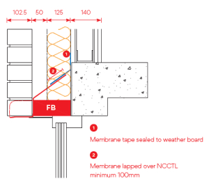
Non-combustible Cavity Trays are tested independently of the internal skin and any other membranes. It is good practice to overlap a strip of membrane, to protect the insulation etc from the elements during construction and in the event of any interstitial condensation forming within the cavity this can be drained out on top of the tray. The membrane should overlap the top of the tray by 100mm. At corners, the strip of membrane should be overlapped and taped as per manufacturer’s technical guidance.
Key:
1. Membrane tape sealed to weather board
2. Membrane lapped over NCCTL minimum 100mm
Key:
1. Membrane tape sealed to weather board
2. Membrane lapped over NCCTL minimum 100mm
Why is it preferable to avoid use of tapes, sealants and mastics when creating joints in Cavity Trays?
The number 1 reason for reopening the cavity wall of a building after occupation is failures in joints of DPC’s and Cavity Trays formed using tapes, sealants and mastics. This can be as a result of workmanship or more often due to onsite conditions impacting the quality of adhesion between materials and tapes, sealants and mastics used to create a watertight joint.
Conditions caused by dust, moisture and temperature are commonly known to adversely impact the performance of tapes, sealants and mastics and therefore the joints formed using them.
Additionally, the integrity of a joint formed using tapes, sealants and mastics cannot be easily checked on site in a non-destructive manner.
The Keyfix ribbed overlapping joints allow for moisture proof joints to be formed without tapes or sealants, whilst also accommodating horizontal movement and allowing for non-destructive quality checking by onsite QC inspectors.
Can a Cavity Tray be cut onsite?
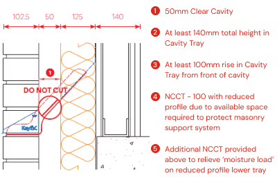
On site cutting and fabrication of Cavity Trays should be avoided at all costs. Fabrication, cutting and folding not carried out by the manufacturer can give rise to warranty disputes. All onsite alterations or fabrications should be signed off by the relevant Warranty Provider and / or the system Manufacturer. If a Cavity Tray clashes with another building component within the cavity (such as a wall tie or wind post), the Cavity Tray may be notched or cut around it, providing approval from the manufacturer has been agreed, and only where the cut / notch does not occur within the nominal 50mm clear cavity.
All cuts should be sealed around using an approved proprietary system.
1. 50mm Clear Cavity
2. At least 140mm total height in Cavity Tray
3. At least 100mm rise in Cavity Tray from front of cavity
4. NCCT - 100 with reduced profile due to available space required to protect masonry support system
5. Additional NCCT provided above to relieve 'moisture load' on reduced profile lower tray
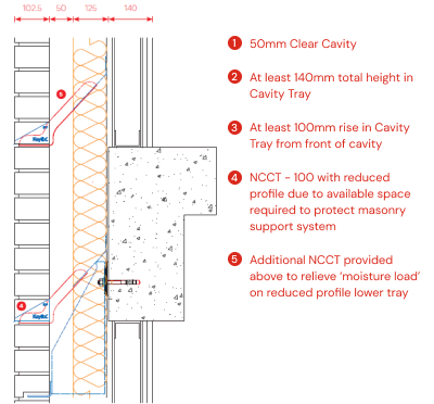
If the space within the cavity does not allow for a standard Cavity Tray profile, can the profile be reduced?
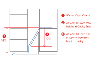
Cavity Trays must conform to predetermined dimensions as shown below in order to perform correctly.
However where the available space within a cavity is restricted due to other components, it may be necessary to reduce the NCCT profile in order to provide protection where it is required. Reducing the NCCT profile below the recommended dimensions will reduce its effectiveness. Consideration must be given to the area of masonry above the tray through which wind driven rain may penetrate.
Where water ingress is considered to be a risk, an additional tray should be installed above to ‘relieve’ the reduced tray.
1. 50mm Clear Cavity
2. At least 140mm total height in Cavity Tray
3. At least 100mm rise in Cavity Tray from front of cavity
4. NCCT - 100 with reduced profile due to available space required to protect masonry support system
5. Additional NCCT provided above to relieve 'moisture load' on reduced profile lower tray
Why is it preferable to have an integral Stop End?
As the water collected on a Cavity Tray builds up it can travel along the horizontal length of the tray or lintel. Unless this movement of moisture is stopped before it gets to the end of the tray or lintel, the moisture can run over the end and back into the cavity or worse into the habitable space.
Proprietary Stop Ends can be adhered to the lintel or tray surface during installation, however this is not easily done and is difficult to supervise or inspect on site.
Site conditions can greatly affect the effectiveness of the adhesion. Cold, wet or dusty surfaces will reduce the quality of adhesion and accordingly the seal created when joining parts onsite.
Mechanically fixed / Integral Stop Ends are manufactured and assembled in a controlled environment and therefore guarantee a watertight joint, ensuring no moisture can escape off the surface of the tray or lintel unless via the intended weep vent.
Why is it preferable to use a Stainless Steel weep vent on a Stainless Steel Cavity Tray?
Only Stainless Steel weep vents can be installed directly on top of a stainless steel Cavity Tray, lintel or masonry support angle without risk of bi-metallic / electrolytic corrosion. Weep vents made from a dissimilar metal must be bedded on top of a layer of mortar to avoid bi-metallic / electrolytic corrosion.
Zinc Alloys can be a concern for some Warranty Providers in relation to corrosive attack from alkali in mortars.
Zinc Alloys can be a concern for some Warranty Providers in relation to corrosive attack from alkali in mortars.
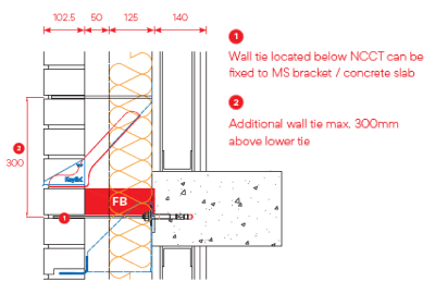
How can wall tie distribution be achieved where Cavity Trays, fire barriers and masonry support are all present together?
Where a Cavity Tray fouls the provision of a wall tie or fixing within the notional 300mm of a masonry support angle or lintel, ties can be installed in courses below the Cavity Tray (fixed to MS brackets or slab edge), with subsequent ties then placed 300mm above this.
Increasing the quantity of wall ties is also good practice.
Key:
1. Wall tie located below NCCT can be fixed to MS bracket/concrete slab
2. Additional wall tie max. 300mm above lower tie
Increasing the quantity of wall ties is also good practice.
Key:
1. Wall tie located below NCCT can be fixed to MS bracket/concrete slab
2. Additional wall tie max. 300mm above lower tie
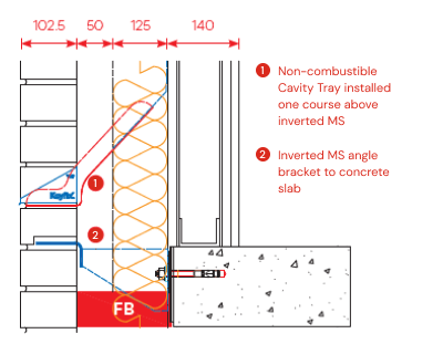
Where is a Cavity Tray positioned when masonry support angle is inverted and positioned at finished floor level?
In cases where inverted masonry support brackets are installed as shown, the NCCT will be installed one course above the masonry support angle and therefore may need to start and stop between openings.
Key:
1. Non-combustible Cavity Tray installed one course above inverted MS
2. Inverted MS angle bracket to concrete slab
Key:
1. Non-combustible Cavity Tray installed one course above inverted MS
2. Inverted MS angle bracket to concrete slab
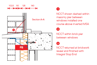
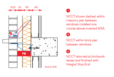
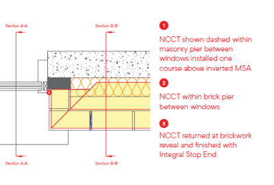
How are window/door reveals detailed?
Where window / door frames are located within the 102.5mm external masonry skin and the NCCT starts and stops between openings, the trays must be finished with an integral Stop End to ensure moisture cannot escape off the tray ends and behind the window / door frames.
Where window / door frames are recessed greater than 102.5mm and the NCCT starts and stops between openings, the trays must return around the brickwork reveal with an integral Stop End in line with masonry / frame jamb.
Key:
1. NCCT shown dashed within masonry pier between windows installed one course above inverted MSA
2. NCCT within brick pier between windows
3. NCCT returned at brickwork reveal and finished with Integral Stop End